Launching Scenes on the Server from a Client
Here is how you can programm turning on/off all reuired lighting using new fucntions of iRidium Mobile 3.0 and Modbus device. You'll need iRidium Server, iRidium Studio and any device with iRidium Client.
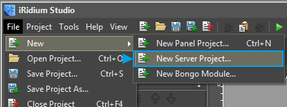
Select "New Server Project" in the Menu.
Give a name to the new project or leave a default one.
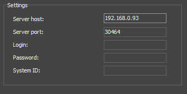
Fill in the following fields in the Settings section for more convenient work:
See description of the other fields see here.
Project Overview enables movement among windows of server settigns:

Project Overview:
In the test example we took a ready project from WIKI2, made in the old version of iRidium GUI Editor
Input connection settings to the controlled equipement in DRIVERS tab:

Nxt we see the following window
Next we describe logics for processing required server fucntions. The following function is used in our project.
2. Name a panel project.
Virtual server channels are assigned as SendNumber with empty Value field.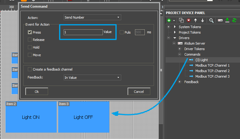
When the light is turned off, send 1, when the light is turned on, send 0.
To test what is programmed above, do the following:
1. Launch the server.
2. Upload a project onto it.
3. Launch/upload a client project.
4. If you don't have read Modbus devices, launch Modbus emulator.
Ready projects (The archive has a server project + a panel project + emulator):
Modbus Light.zip
1. Create a server project
more about creating a server project here.1. Create a File of a Server Project
Select "New Server Project" in the Menu.
2. Name a Project.
Give a name to the new project or leave a default one.
3. Input Settings of Connection to the Server.
Input basic information about a project and settings of connection to the server (can be input later).Fill in the following fields in the Settings section for more convenient work:
- Server host - server IP address
- Server port - port for connecting to the server (by default it is 30464)
- Login (function is under development) - loging for connecting control panels to the server
- Password (function is under development) - password for connecting control panels to the server
- System ID (function is under development) - a unique identifier of a server that will be used in push-notifications system and in DDNS server.
See description of the other fields see here.
4. Go to I/O Tab
(more about tabs here):Project Overview enables movement among windows of server settigns:

Project Overview:
- I/O - Input/Output; opens server tags and driver tags for editing.
- Config - settings of a server project.
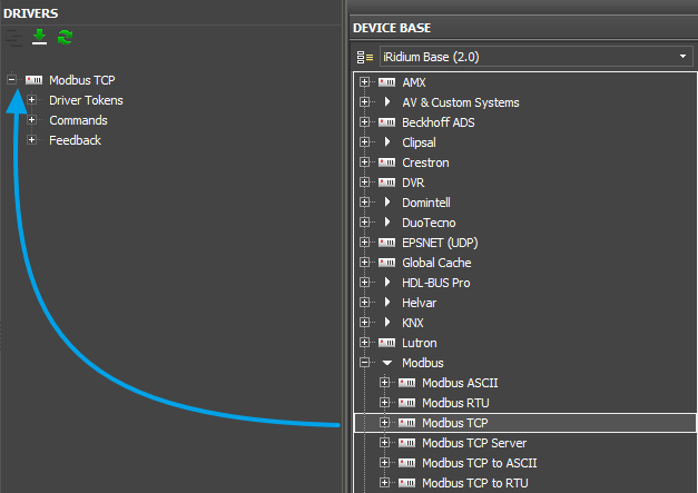
5. Add Modbus TCP driver from device base
5. Input Settings of Connection to Equipment:
If you imported drivers from *.irpz project created earlier in iRidium GUI Editor, the settings for it are already input.In the test example we took a ready project from WIKI2, made in the old version of iRidium GUI Editor
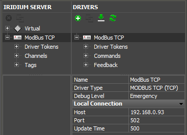
Input connection settings to the controlled equipement in DRIVERS tab:
- Name - name of controlled equipment (any)
- Debug Level - notification to be displayed in the server log
- Local Connection - fill in the list of connection settings, it's unique for each driver
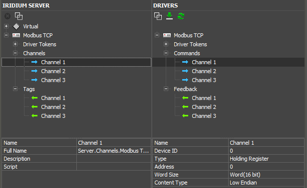
7. Set up up control commands and feedback channels:
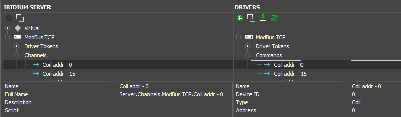
Set up commands and feedback channesl in DRIVERS panel the same way it is done in Project Device Panel of a panel project. Manual on Modbus driver is in Wiki V2A server channel (for recording) or server tag (for reading) is formed for each command and feedback channel in IRIDIUM SERVER panel. iRidium Server driver is formed on their basis, and each control panel that will connect to this server, will address these channels and tags.
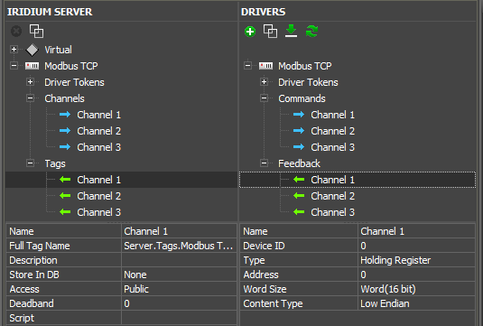
Fields of a Server channel that can be set up (for writing):
Fields of a Server channel that can be set up (for writing):
- Name - short name (by default: name of a driver command)
- Full Name - full name of a server channel to call from script
- Description - description (optional)
- Script - do JavaScript function without agruments each time when a channel is activated
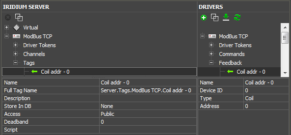
- Name - short name (by default: name of driver feedback channel)
- Full Tag Name - full name of a server tag to call from script
- Description - description (optional)
- Store In DB - saving all changed values in the database
- Access - type of variable: Public - can be changed from a control panel, Private - can be changed from the server
- Deadband - measurement inaccuracy, that is not take into account when making a chart on the basis of tag data.For example, if Deadband is 0.5, change of variable by 0.3 is not displayed in the chart in the client-app.
- Script - do JavaScript function each time when a tag is activated.
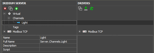
1 Virtual channel with "Light" name
3 Channel with set addresses
3 feedback channels with set addresses
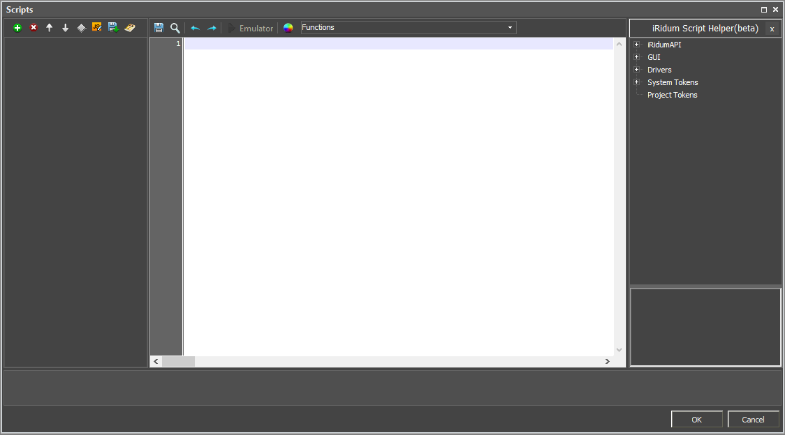
8. Write logics that script will process
Go to JavaScript windowNxt we see the following window
Next we describe logics for processing required server fucntions. The following function is used in our project.
IR.AddListener(IR.EVENT_START,0,function()
{
//Lsunch a listener of the basis if global tag work.
IR.SetGlobalListener(IR.EVENT_GLOBAL_TAG_CHANGE, function(name, value)
   {

      IR.Log("Active global: " + name + "\tЗначение: " + value);
      /*
      Write logics for required processing. In our case it's the following.
      If command name corresponds to our channel and its value is 1, we change value to 0 and the light is turned off.
      */
      if (name == "Server.Channels.Light" && value == 1)
         {
             IR.Log("Light OFF")
             IR.SetVariable("Server.Channels.Modbus TCP.Channel 1", 0)
             IR.SetVariable("Server.Channels.Modbus TCP.Channel 2", 0)
             IR.SetVariable("Server.Channels.Modbus TCP.Channel 3", 0)
         }else
      /*
      Write logics for required processing. In our case it's the following.
    If command name corresponds to our channel and its value is 0 we change value to and the light is turned on.
      */
      if (name == "Server.Channels.Light" && value == 0)
         {
             IR.Log("Light ON")
             IR.SetVariable("Server.Channels.Modbus TCP.Channel 1", 1)
             IR.SetVariable("Server.Channels.Modbus TCP.Channel 2", 1)
             IR.SetVariable("Server.Channels.Modbus TCP.Channel 3", 1)
         }
   });
//Signature block for required tags
IR.SubscribeTagChange("Server.Channels.Light");
IR.SubscribeTagChange("Server.Tags.Modbus TCP.Channel 1")
IR.SubscribeTagChange("Server.Tags.Modbus TCP.Channel 2")
IR.SubscribeTagChange("Server.Tags.Modbus TCP.Channel 3")
});
9. Save a project .
2. Make a panel project
1. Add server channels and tags to a panel project
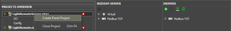
There are several ways to do it:1. Make a panel project from a server project
1. Open your server project. Click with a right mouse button on the project name and select "Create Panel Project".2. Name a panel project.
3. iRidium Server driver is in "Project Device Panel" of a panel project, The driver has connection settings to a server project (if you set them before), as well as all channels and tags.
2. Assign commands to graphical items
Driver commands and feedback, as well as driver tokens are assigned to graphical items the way it is done with all other drivers according to the manual at iRidiumWiki.Virtual server channels are assigned as SendNumber with empty Value field.
When the light is turned off, send 1, when the light is turned on, send 0.
To test what is programmed above, do the following:
1. Launch the server.
2. Upload a project onto it.
3. Launch/upload a client project.
4. If you don't have read Modbus devices, launch Modbus emulator.
Ready projects (The archive has a server project + a panel project + emulator):
Modbus Light.zip
Customer support service by UserEcho