iRidium Server + HDL
Read more about HDL driver here http://wiki2.iridiummobile.ru/HDL-BUS_Pro.
Stages of making a project to control HDL equipment with the help of iRidium Server:
1. Creation of a server project. Import of control channels, setup of connection to equipment. Creation of script scenes, setup of record to the database.
2. Creation of panel project connected to a server project. Creation of a graphic interface of the project. Connection of a graphic interface to channels and control tags.
3. Uploading of a server project onto the server.
4. Uploading of a panle project into the client.
For fast transition from version 2.2. to the server version use a project created earlier in iRidium GUI Editor.
Projects to study: a server project and a panel project connected with it:
Input fields in the Settings section for more convenient work:
You can read about the other fields here.
Project Overview allows you to move among windows of server settings:

Project Overview:
Access to Scanning function is done with the help of Scanning function in the DRIVERS panel:
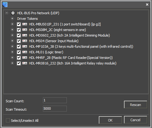 If you can't scan, use pre-set devices in iRidium base. First add HDL-BUS Pro Network (UDP), then add required device to the Network:
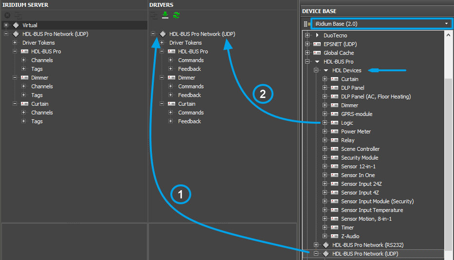
It includes:
SendTimeOut - obligatory interval between commands sent by a control panel to HDL IP module (allows to decrease the load on the IP module and the HDL bus)
Broadcast - 255.255.255.255 – address broadcast for data exchange with HDL
Fields of a Server channel that can be set up (for writing):
1. Create 2 virtual channels and 1 virtual tag with the right mouse button:
2. Go to JS Editor. Create a script file with required functions:
Stages of making a project to control HDL equipment with the help of iRidium Server:
1. Creation of a server project. Import of control channels, setup of connection to equipment. Creation of script scenes, setup of record to the database.
2. Creation of panel project connected to a server project. Creation of a graphic interface of the project. Connection of a graphic interface to channels and control tags.
3. Uploading of a server project onto the server.
4. Uploading of a panle project into the client.
For fast transition from version 2.2. to the server version use a project created earlier in iRidium GUI Editor.
Projects to study: a server project and a panel project connected with it:
1. Make a server project
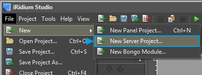
More about creation of a server project here1. Create a file of a server project
Select "New Server Project" in the menu.2. Name the project
Give a name to the server project or leave a default one.3. Enter settings of connection to the server
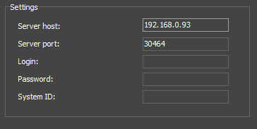
Enter the basic information about the project and settings of connection to the server (can be input later).Input fields in the Settings section for more convenient work:
- Server host - IP address of the server
- Server port - port of connection to the server (by default: 30464)
- Login (function under development) - login to connect panels to the server
- Password (function under development) - password to connect panels to the server
- System ID (function under development) - a unique identificator of a server, that will be used in push-notification system and in DDNS server.
You can read about the other fields here.
4. Go to I/O tab
(more about tabs here):Project Overview allows you to move among windows of server settings:

Project Overview:
- I/O - inputs/outputs; opens server tags and driver tags for editing.
- Config - settings of a server project
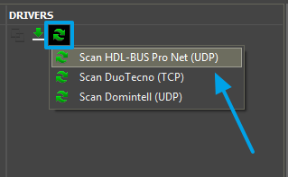
5. Add HDL driver to the project
HDL driver is usually added with the help of Scanning function.Access to Scanning function is done with the help of Scanning function in the DRIVERS panel:
6. Input connection settings to equipment:
If you used the scanning function, driver settings are already filled in. Input only settings of the Network.It includes:
SendTimeOut - obligatory interval between commands sent by a control panel to HDL IP module (allows to decrease the load on the IP module and the HDL bus)
Broadcast - 255.255.255.255 – address broadcast for data exchange with HDL
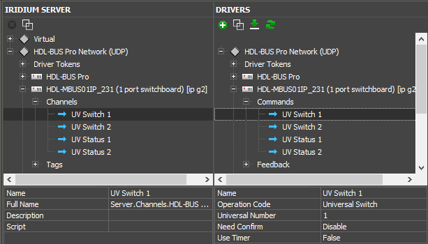
7. Setup commands to control equipment and feedback channels:
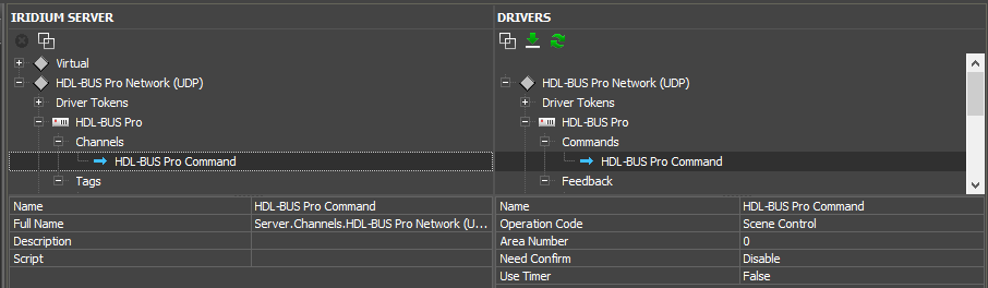
A server channel (for recording) or server tag (for reading) is formed for each command and feedback channel in IRIDIUM SERVER panel. iRidium Server driver is formed on their basis, and each control panel that will connect to this server, will address these channels and tags.Fields of a Server channel that can be set up (for writing):
- Name - short name (by default: name of a driver command)
- Full Name - full name of a server channel to call from script
- Description - description (optional)
- Script - do JavaScript function without agruments each time when a channel is activated
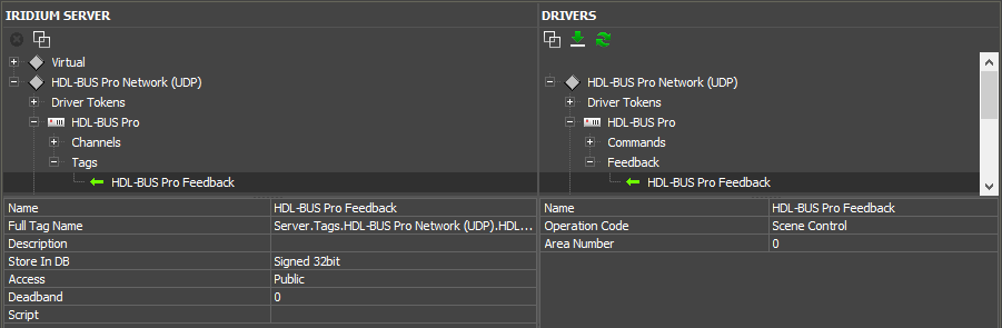
- Name - short name (by default: name of driver feedback channel)
- Full Tag Name - full name of a server tag to call from script
- Description - description (optional)
- Store In DB - saving all changed values in the database
- Access - type of variable: Public - can be changed from a control panel, Private - can be changed from the server
- Deadband - measurement inaccuracy, that is not take into account when making a chart on the basis of tag data.For example, if Deadband is 0.5, change of variable by 0.3 is not displayed in the chart in the client-app.
- Script - do JavaScript function each time when a tag is activated.
!In the current beta version of iRidium Studio there is no capability to synchronize names of drivers, channels and tags, sso give them final names during current setting. As, when you start making a panel project and after it decide to give another name to a driver, channels or tags in IRIDIUM SERVER panel during synchronization they will be added as a new driver, a new channel or new feedback and you'll have to assign them to graphical items of an interface one more time.
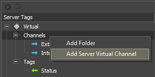
8. Create Virtual Variables (optional):
Virtual variables (Virtual) are variables, where any data, received as a result of script work (numbers, lines, arrays) can be recorded. Virtual variables are available for editing from a control panel.- VIrtual > Channels - variables available for writing
- VIrtual > Tags - variables available for reading
1. Create 2 virtual channels and 1 virtual tag with the right mouse button:
2. Go to JS Editor. Create a script file with required functions:
function External_KNX_IP()
{
 IR.Log("External KNX IP"); //puts into the server log
 IR.GetDevice("KNX").SetParameters({Host: "192.168.0.152", Port: "3671", ConnectTime: "120000", SendTime: "0", PingTime: "60000"}); // changes settings of connection to the driver
 IR.SetVariable("Server.Tags.Status","We try to connect to External KNX IP"); //records text into Status virtual tag
};
function Internal_KNX_IP()
{
 IR.Log("Internal KNX IP"); //puts into the server log
 IR.GetDevice("KNX").SetParameters({Host: "213.114.30.30", Port: "3671", ConnectTime: "120000", SendTime: "0", PingTime: "60000"}); // changes settings of connection to the driver
 IR.SetVariable("Server.Tags.Status","We try to connect to Internal KNX IP"); //records text into Status virtual tag
};
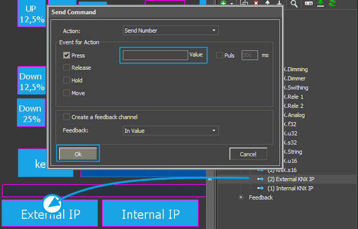
3. Select the required function for both commands in the Script field of the required command.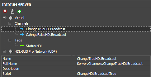
9. Write Required Script (optional).
Read here how to call channels and tags of a server project.10. Save a Project.
HDL Server.sirpz2. Make a panel project
1. Add server channels and tags to a panel project
There are several ways to do it:1. Make a panel project from a server project
1. Open your server project. Click with a right mouse button on the project name and select "Create Panel Project".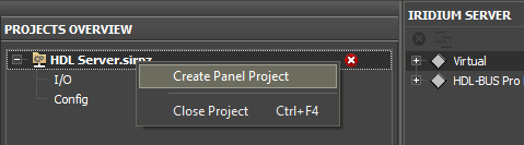
2. Name a panel project.
3. iRidium Server driver is in "Project Device Panel" of a panel project, The driver has connection settings to a server project (if you set them before), as well as all channels and tags.
2. Synchronize iRidium Server driver with an existing panel project
2. Make a new panel project or open an existing panel project in iRidium Studio.
3. iRidium Server driver can be added to a panel project:
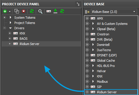
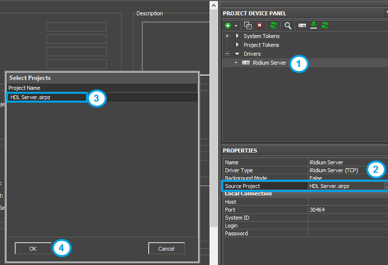
- 4. Choose your server project as the source of iRidium Server driver:
- Select iRidium Server driver in "Project Device Panel".
- Press ... in Source Project line of the driver settings.
- Select the required server project in the list.
- Press ОК.
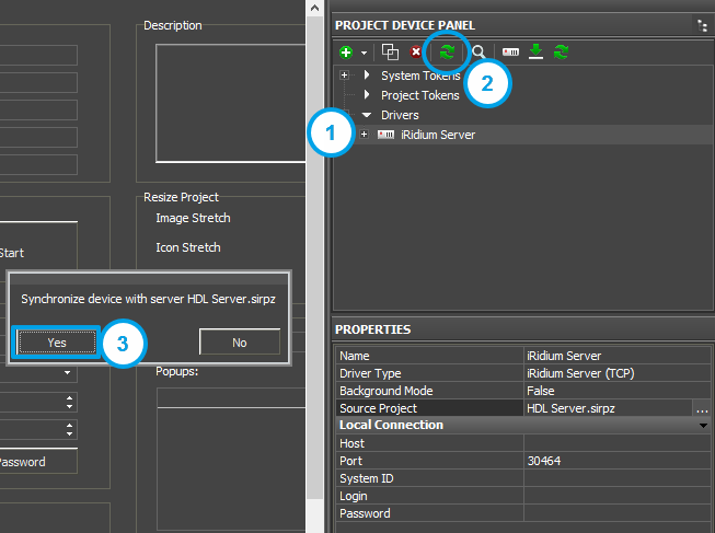
- Select iRidium Server driver in "Project Device Panel"
- Press Synchronization icon.
- Agree with the synchronization request.
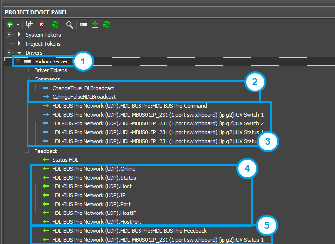
- 1 - Driver Tokens are driver variables, they display connection status to the driver. The driver variables are available only for reading:
- Online - connection status to the driver (Online/Offline = 1/0)
- Status - connection status to the driver (Offline/Connecting/Online/Waiting = 0...3)
- Host - domain name of a remote system доменное имя удаленной системы
- IP - IP-address of a control panel
- Port - local client port for connection to a remote device
- HostIP - IP-address of a remote system, to which iRidium App is connected
- HostPort - port of a remote system to which iRidium App is connected
- ServerName - name of a server
- ServerModel - model of a server
- ServerHWID - identificator of a server
- ServerFamily - family code of the operation system
- ServerArch - code of architecture (1 - x86; 2 - x64-86; 3 - ARM32)
- ServerFamillyName - family name of operation system
- ServerArchName - architecture name of operation system
- ServerOsName - full name of operation system
- ServerVersion - version of a server
3. Virtual server channels.
4. Tokens of a driver, controlled via the server.
5. Feedback tags of drivers controlled via the server.
6. Virtual server tags.
!Don't make new commands and feedback channels in iRidium Server driver in a panel project. They won't be saved in a server project during synchronization and won't work.
Parameters of a server command in a panel project:
Name - name of channel. It has the following format "Driver name.Channel name"
Parameters of a server tag in a panel project:
Name - name of tag. It has the following format "Driver name.Tag name"
Save Value When Disconnect - saving the last received tag value on the button, when connection to the server is lost. (True - save value on the item; False - set value to 0);
2. Assign commands to graphical items
Driver commands and feedback, as well as driver tokens are assigned to graphical items the way it is done with all other drivers according to the manual at iRidiumWiki.Virtual server channels are assigned as SendNumber with empty Value field.
Virtual server tags are assigned as As Value or As Text, depending on the purpose.
3. Synchronize a server and a panel project during work
If you want to correct a server project during your work at a panel project, you'll have to synchronize these projects.In the current iRidium Studio version synchronization can:
+ add new channels and tags from a server project;
synchronization can't:
- update names of drivers, server channel and server tag (if you change the name of an existing channel or tag, it will be added again with a new name);
- delete channels and tags in a panel project, if they are deleted from a server project;
Synchronization process:
1. Change a server project and save it.
2. Go to a panel project connected with the server project and:
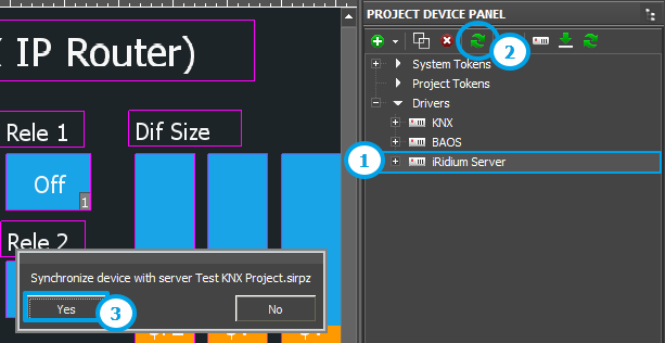
- Select iRidium Server driver in "Project Device Panel".
- Press Synchronization icon.
- Agree with the Synchronization request.
When a server project and a panel project are fully ready, they have to be uploaded to the server and to panels.
How to upload a server project onto iRidium Server
Customer support service by UserEcho