How to Make a Server Project in iRidium Studio
iRidium Server Project is a project file, created in iRidium Studio. It consists of a driver part (commands to control equipment), virtual server commands, script channels and files (not necessary). iRidium Server project have the following format *.SIRPZ, it is uploaded onto iRidium Server.
The described example of creating a server project is given on the basis of a working KNX installation created earlier. The driver to control equipment is imported from a project created in iRidium GUI Editor V.2.* earlier.
Steps to make an iRidium Server project:

1. Form on the server a list of equipment to control: set up drivers, create a list of commands and feedback channels.
2. All commands and channels are automatically projected onto the server variables. A control panel with iRidium can address these variables.
3. Set up scripts: create modifire-functions to transform data into data variables and etc.
4. Transfer server variables to a project for a control panel. The variables will be available as "iRidium Server".
5. Set up scripts for a control panel (if necessary).
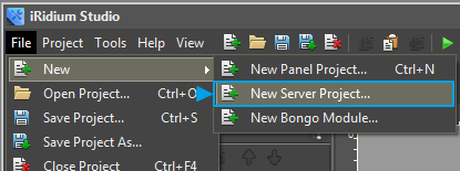
Select "New Server Project" in the Menu.
Give a name to the new project or leave a default one.
Fill in the following fields in the Settings section for more convenient work:
See description of the other fields see here.
Project Overview enables movement among windows of server settigns:

Project Overview:
1. Addition of Drivers from Device Base
It's available to all drivers supported by iRidium.
Drivers are added by drag-n-drop from the DEVICE BASE tab onto free space of the working area of the DRIVERS tab (in the field UNDER virtual tags).
2. Import
Access to import function is done from File->Import menu and with the help of Import button in the DRIVERS tab.
The IMPORT function enable to import into a project the following:
Acess to scanning function is done with the help of Scanning function in the DRIVERS panel.
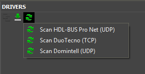
The scanning function scans your local net and forms drivers to control the following devices:
Set up commands and feedback channels in the DRIVERS panel the same way they are set up in the Project Device Panel of a panel project. Manual on working with every driver are here Wiki V.2
If you imported a project created earlier, commands and feedback channels are already set.
For each command and feedback channel a server channel (for recording) or a server tag (for reading) is formed in Server Tags panel. iRidium Server driver is formed on their basis, and every control panel, connected to this server, will address these channels and tags.
Fields to set up for a server channel (for recording):
2. Go to JS Editor. Create a script file with required functions:
Read the next article How to connect a server project to a panel project.
The described example of creating a server project is given on the basis of a working KNX installation created earlier. The driver to control equipment is imported from a project created in iRidium GUI Editor V.2.* earlier.
Steps to make an iRidium Server project:

1. Form on the server a list of equipment to control: set up drivers, create a list of commands and feedback channels.
2. All commands and channels are automatically projected onto the server variables. A control panel with iRidium can address these variables.
3. Set up scripts: create modifire-functions to transform data into data variables and etc.
4. Transfer server variables to a project for a control panel. The variables will be available as "iRidium Server".
5. Set up scripts for a control panel (if necessary).
1. Create a File of a Server Project
Select "New Server Project" in the Menu.
2. Name a Project.
Give a name to the new project or leave a default one.
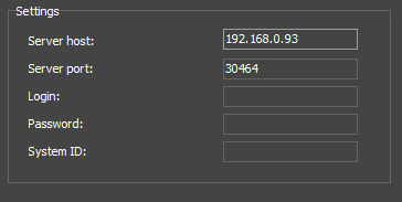
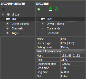
3. Input Settings of Connection to the Server.
Input basic information about a project and settings of connection to the server (can be input later).Fill in the following fields in the Settings section for more convenient work:
- Server host - server IP address
- Server port - port for connecting to the server (by default it is 30464)
- Login (function is under development) - loging for connecting control panels to the server
- Password (function is under development) - password for connecting control panels to the server
- System ID (function is under development) - a unique identifier of a server that will be used in push-notifications system and in DDNS server.
See description of the other fields see here.
4. Go to I/O Tab
(more about tabs here):Project Overview enables movement among windows of server settigns:
Project Overview:
- I/O - Input/Output; opens server tags and driver tags for editing.
- Config - settings of a server project.
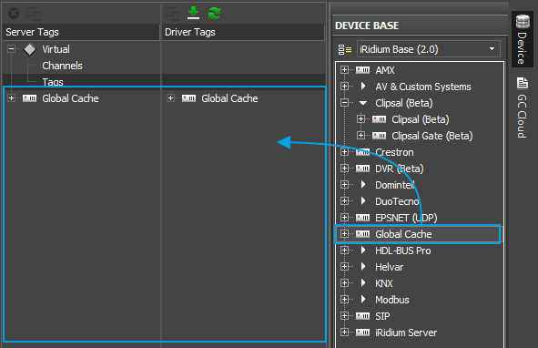
5. Add Required Drivers to the Project
Drivers are stored in the Driver Tags panel in a server project. Drivers are added to a server project the same way drivers are added to a panel project:1. Addition of Drivers from Device Base
It's available to all drivers supported by iRidium.
Drivers are added by drag-n-drop from the DEVICE BASE tab onto free space of the working area of the DRIVERS tab (in the field UNDER virtual tags).
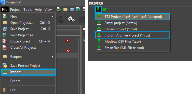
2. Import
Access to import function is done from File->Import menu and with the help of Import button in the DRIVERS tab.
The IMPORT function enable to import into a project the following:
- ETS Project - a list of group addresses and datapoints, formed in ETS;
- Simple project - joins from from Crestron SIMPL™ Windows® Software.
- Clipsal project - group addresses from C-Bus Toolkit.
- Iridium Archive Project (*irpz) - drivers from iRidium projects created earlier. For example, you can add to a server project a driver created in iRidium GUI Editor v2.*, it enables you to transfer a working project to a server.
- Modbus CSV (*.csv) - channels for Modbus driver, formed in Microsoft Excel.
Acess to scanning function is done with the help of Scanning function in the DRIVERS panel.
The scanning function scans your local net and forms drivers to control the following devices:
- HDL-BUS Pro.
- Duotecno.
- Domintell.
5. Input Settings of Connection to Equipment:
If you imported drivers from *.irpz project created earlier in iRidium GUI Editor, the settings for it are already input.6. Set up Commands to Control Equipment and Feedback Channels:
Set up commands and feedback channels in the DRIVERS panel the same way they are set up in the Project Device Panel of a panel project. Manual on working with every driver are here Wiki V.2
If you imported a project created earlier, commands and feedback channels are already set.
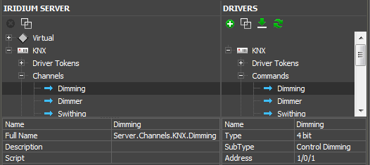
7. Set up Server Channels and Tags Assigned to the Driver:
For each command and feedback channel a server channel (for recording) or a server tag (for reading) is formed in Server Tags panel. iRidium Server driver is formed on their basis, and every control panel, connected to this server, will address these channels and tags.
Fields to set up for a server channel (for recording):
- Name - short name (by default it is a name of a driver command)
- Full Name - full name of a server channels for calling from script
- Description - description (optional)
- Script - do JavaScript function without arguments every time a channel is activated.
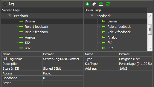
- Name - short name (by default it's a name of a driver feedback channel)
- Full Tag Name - full name of a server tag for calling from script
- Description - description (optional)
- Store In DB - saving all changed values in database
- Access - type of variable: Public - can be changed from a control panel, Private - can be changed only from the server
- Deadband - measument accuracy, that is ignored when building trends on the basis of tag data. For example, if Deadband is 0.5, the variable change of 0,3 is not displayed on the trend in the client app. (A symbol to devide a whole number from a fraction depends on the regional settings of your computer. If the devision symbol is a comma, the number looks like this 0,3 or 0,5, if it's a point, it looks like this 0.3 and 0.5)
- Script - do JavaScript function without arguments every time a tag is activated.
!In the current beta version of iRidium Studio there is no capability to synchronize names of drivers, channels and tags, sso give them final names during current setting. As, when you start making a panel project and after it decide to give another name to a driver, channels or tags in IRIDIUM SERVER panel during synchronization they will be added as a new driver, a new channel or new feedback and you'll have to assign them to graphical items of an interface one more time.
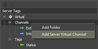
8. Create Virtual Variables (optional):
Virtual variables (Virtual) are variables, where any data, received as a result of script work (numbers, lines, arrays) can be recorded. Virtual variables are available for editing from a control panel.
1. Create 2 virtual channels and 1 virtual tag with the right mouse button:
- VIrtual > Channels - variables available for recording
- VIrtual > Tags - variables available for reading
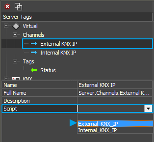
1. Create 2 virtual channels and 1 virtual tag with the right mouse button:
2. Go to JS Editor. Create a script file with required functions:
function External_KNX_IP()
{
 IR.Log("External KNX IP"); //puts into the server log
 IR.GetDevice("KNX").SetParameters({Host: "192.168.0.152", Port: "3671", ConnectTime: "120000", SendTime: "0", PingTime: "60000"}); // changes settings of connection to the driver
 IR.SetVariable("Server.Tags.Status","We try to connect to External KNX IP"); //records text into Status virtual tag
};
function Internal_KNX_IP()
{
 IR.Log("Internal KNX IP"); //puts into the server log
 IR.GetDevice("KNX").SetParameters({Host: "213.114.30.30", Port: "3671", ConnectTime: "120000", SendTime: "0", PingTime: "60000"}); // changes settings of connection to the driver
 IR.SetVariable("Server.Tags.Status","We try to connect to Internal KNX IP"); //records text into Status virtual tag
};
3. Select the required function for both commands in the Script field of the required command.9. Write Required Script (optional).
Read here how to call channels and tags of a server project.10. Save a Project.
Test KNX Project.sirpzRead the next article How to connect a server project to a panel project.
Customer support service by UserEcho